|
UNDERSTANDING MODAL
PARAMETER TECHNOLOGY AND MODE SHAPE SCALING
By Brett A. Brinkman and David J.
Macioce
Structural Measurement Systems,
Inc.
ABSTRACT
Modal analysis has become a frequently
used method for studying the dynamic behavior of mechanical
structures. This technique is usually presented using parameters
which are defined by complicated mathematical derivations.
Unfortunately, it is difficult for the experimentalist to apply
these mathematical concepts to the solution of his vibration
problem. Consequently, modal analysis has become a "black box".
technique with frequency response measurements as input and mode
shapes as the output. To examine this "Black box", and in particular
mode shape scaling, we present an illustrative example that relates
both the terminology and mathematical concepts to practical
applications.
INTRODUCTION
For our example, we will determine the modal parameters of a set
of measurements which were acquired from the structure shown in
Figure 1. To better exemplify an actual modal test we will assume
that the physical properties of the test structure (eg. mass,
stiffness) are unknown. Because mode shape scaling is critical to
further data analysis (eg. structural modification), it will be
explained in detail.
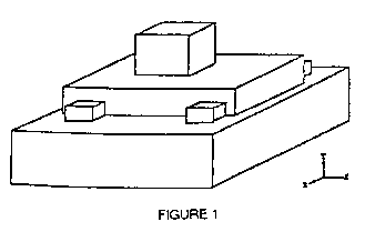
Although the structure is a continuous system, we will model it
as a system of three discrete elements. For simplicity, we will
assume the vibratory motion is in the ydirection only. This
simplifies the model to the three degreeoffreedom system
shown in Figure 2.

FREQUENCY RESPONSE MEASUREMENTS
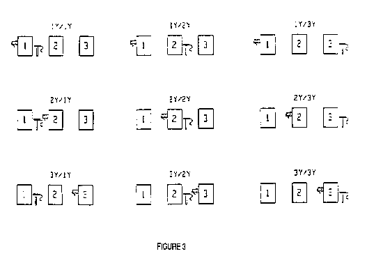
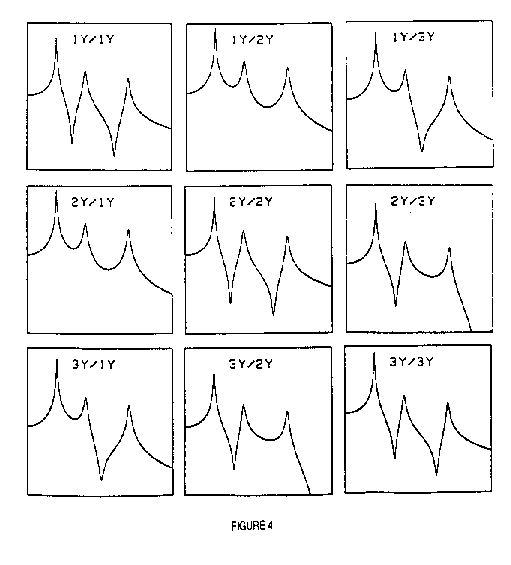
Because we are modeling the test structure as a
threedegreeoffreedom system, nine frequency response
measurements completely define its dynamic characteristics. For our
example, we will assume that the frequency response data has already
been gathered and that the response units are inches and the force
units are pounds. Figure 3 is an illustration of the force and
response transducer positions and Figure 4 is a matrix of the
measurements acquired from those configurations.
FREQUENCY AND DAMPING
We can now extract the modal parameters from the frequency
response measurements. The frequency and damping must be determined
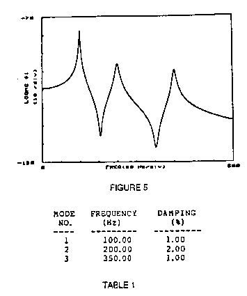
first. We will use a measurement in which the peaks are well
defined, such as measurement 1y/1y shown in Figure 5.
The measurement in Figure 5 contains three peaks. These peaks
correspond to the three modes of the structure. The frequency and
damping of each of these modes was found using standard curve
fitting techniques and are listed in the Table 1.
Frequency and damping are global properties. This means that they
do not vary across the structure, and can be estimated from any
frequency response measurement taken from the structure except those
measured at any point where the mode shape has zero amplitude.
MODE SHAPES
Now, we will use the amplitude of the peaks to determine the mode
shapes. The amplitude of the first peak of each measurement in
Figure 4 is listed in Figure 6.
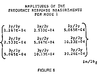
Scaling the three columns of the above matrix such that the
smallest element of each column is equal to one (ie. dividing each
element of a column by the smallest element of that column), yields
the modal vectors shown in Figure 7.
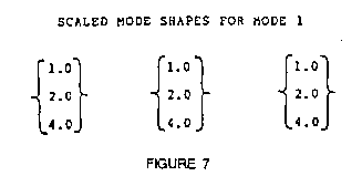
We can also scale the rows in a similar manner and obtain a
matrix with the mode shape (1, 2, 4) in each row. We can see from
this scaling exercise that the complete mode shape is defined in
every column and row. Given this and recalling that the frequency
and damping can be determined from any measurement, we can conclude
that we need only measure one row or one column of the frequency
response matrix to completely define all the modal parameters.
Now referring to Figure 3, we can describe this property as it
relates to a modal test. A column of the frequency response matrix
contains measurements acquired by fixing the location of the input
force and moving the response to each test point. Similarly, a row
contains measurements acquired by fixing the response location and
moving the input to each test point.
The ramifications of this property of the frequency response
matrix are that we need not measure all nine frequency response
measurements to obtain the modal parameters. By selecting one
exciter location and measuring the response at all three points or
by fixing the response location and exciting the structure at all
three points, we can obtain all of the structure's modal parameters.
From this point on we will assume that we only have data for the
first column of the frequency response matrix. This means that we
have taken data with the exciter located at mass #1 and the response
measured at all three masses. Now let's take a closer look at the
scaling of the mode shapes.
The mode shape in Figure 8 is scaled but uncalibrated. This means
that it is scaled to a convenient format (in this case, the
convenience is for ease of reading) but not calibrated to the
frequency response measurements. This mode shape can be used for
plotting or animated display.
The amplitudes in Figure 9 are an unscaled but calibrated mode
shape. This means that the mode shape values are directly related to
the frequency response measurements but are not scaled to a
convenient format.
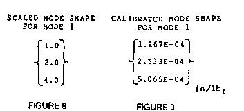
For users that require only frequency, damping, and a display of
the mode shape, an uncalibrated mode shape (ie. Figure 8) is
sufficient, regardless of how it is scaled. However, for advanced
analysis techniques such as structural dynamics modification, the
mode shape must be calibrated and scaled so that the correct
inertial and elastic properties of the structure are preserved. In
our example, the mode shapes will be calibrated and scaled using two
techniques.
MODE SHAPE SCALING
The first scaling technique is based on an expression which
relates the peak values of the frequency response measurements to a
scaled calibrated mode shape. This expression, known as a residue,
is related to the frequency response measurements by a term
proportional to the damping at the natural frequency. The residues
were computed from our example data using a standard curve fitting
method, and those for mode #1 are shown in Figure 10.
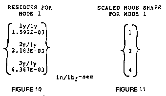
Scaling the residues such that the smallest element is equal to
one (ie. dividing each element by the smallest element) yields the
same mode shape as that obtained previously (See Figure 11). This
shows that the unscaled calibrated mode shape can be either the
amplitudes of the frequency response measurements or the residues.
The advantage of using the residues is that they provide a
convenient way to scale the mode shapes while retaining the
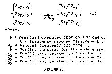
calibration. If we look closely at the residues we see that each one
is actually comprised of three values; a calibration constant, and
two coefficients which provide the scaling. The composition of the
residues, for mode 1 of our example, is shown in Figure 12.
UNITY MODAL MASS SCALING
In general, each equation in Figure 12 contains three unknowns.
In the third equation, for example, M, U1y and
U3y are unknown while the residue
R1y/1y and the natural frequency wd are known.
However, if a measurement is taken at a "driving point". (ie. the
force and response measured at the same location), the coefficients
are repeated, thus reducing the number of unknowns to two for that
particular equation. The driving point which we will use in our
example is measurement 1y/1y. Figure 13 shows
that the first equation has only two unknowns, M and U1y.

If we solve for U1y we have the solution in terms of the residue
R1y/1y the natural frequency wd, and a scaling
constant M. Now, if we arbitrarily choose the scaling constant M to
be unity, then we can solve for U1y. Once U1y
is known, the other mode shape coefficients can be determined. These
coefficients comprise the scaled calibrated mode shape.
In Figure 13, the scaling constant M is known as the "Modal
mass". For the single degreeoffreedom case, the mode shape
coefficient U1y is equal to one (1 ) and the expression
for modal mass is the actual mass of the structure. Of course, this
is a theoretical case and in the actual case the value of M is
related to how the mode shape is scaled. In our case we arbitrarily
set the value of M to unity and scale the mode shape accordingly.
This technique is known as unity modal mass scaling.
SCALING THE MODE SHAPES USING EFFECTIVE
MASS/STIFFNESS
In the second technique, the mode shape scaling is completely
arbitrary. This means that the mode shape itself does not contain
any calibration information. Rather, a calibration constant is
computed for a particular measurement and mode. To demonstrate this,
we will use the mode shape shown in Figure 8. Recall that this mode
shape is scaled but not calibrated. To calibrate this mode shape we
will compute the residue for a particular point and tag it to the
corresponding degree of freedom.
The residue for mode #1 of measurement
1y/1y, computed using a standard curve fitting
method, is 1.592E03 in/lbf. Since we know the relative
amplitudes for the rest of the mode shape, this residue provides the
calibration for the entire mode shape. Therefore, by calculating the
residue for one test point and tying it to one value of the mode
shape, we retain the calibration for the entire mode shape. Recall
that for the single decree of freedom case, the mode shape
coefficients in equation 2 are equal to one. Rearranging this
reduced equation gives the modal mass in terms of the residue and
natural frequency only (equation 3).

Using the relationship, w2 = K/m, together with
equation 3 allows us to also represent the modal stiffness in terms
of the natural frequency and residue (equation 4). Like modal mass,
the term modal stiffness originated from the single
degreeoffreedom model. For the multiple
degreeoffreedom case these values are the calibration for
the mode shape. Some users have been able to use this value when
approximating a single degreeoffreedom case, hence they
are also called effective mass and the effective stiffness. This
approximation is highly dependent on the type of structure being
tested and in not normally made.
SUMMARY
This parameter estimation example was presented to explain the
modal analysis process following the acquisition of the frequency
response measurements. By closely examining the frequency response
matrix, we found that not all of the measurements are needed to
completely define a structure's dynamic characteristics. This
property greatly simplifies the data acquisition process. It was
shown that the frequency and damping could be extracted from any
measurement in which the mode shape values are nonzero.
Mode shapes were discussed both in terms of generating a display
and using them for further data analysis. Two mode shape scaling
techniques were described to show that mode shape scaling is
arbitrary as long as the inertial and elastic properties are
preserved.
REFERENCES
1. Brown, D.L.; Allemang R.A.; Zimmerman, R.; Mergeay, M.;
"Parameter Estimation Techniques for Modal Analysis" SAE Paper
Number 790221, SAE Transactions, Volume 88, 1979, pp. 909 914.
2. Formenti, D.L.; "Analytical and Experimental Modal Analysis",
May 1977 Modal Analysis Course, University of Cincinnati.
3. Klosterman, A.; McClelland, W.A.; "Combining Experimental and
Analytical Techniques for Dynamic System Analysis"; Structural
Dynamics Research Corporation, 1973, 20 pp.
4. Richardson, M.H.; "Modal Analysis Using Digital Test Systems";
Proceedings of Seminar on Understanding Digital Control and Analysis
In Vibration Test Systems, May 1975.
|